ECU REPAIR TOOL(FULL)

ENGINEERS’ POWERFUL ASSISTANT
Equipment Description
NED―3058,testing-analyzing equipment of automobile’s EECS and ECU, is specially designed for engineers who repair automobile’s EECS and ECU. It is a handset and also can be used at worktable. It includes electric-control analyzing equipment and signal generator. According to the common characteristic if automobile’s EECS, the equipment can simulate 8 kinds of signals to meet the demands of diagnosing work. Moreover, the equipment can simulate 3 kinds of independent, changeable signal combination at the same time. The equipment is designed on the basis of electric-control principle and repairing regularity, so it can also be a useful teaching tool to grasp Automobile-Electric technique in automobile repairing skill training.
Brief Introductions of Functions
Panel’s Display:
1,Digital display of signal’s frequency.
2,Strip display of DUTY.
3,LED display of signal output.
4,Digital display of injection pulse width.
5,Strip display of output voltage.
6,LED display of drive signal output.
7,LED display of external signal input.
The function of simulating sensor signal:
1,58+2 signal (58Hz―900Hz), simulate crankshaft position signal. Have 2 shifts: 5Vpp, 10Vpp.
2,Sin wave signal (20Hz―900Hz), simulate car speed, gear speed, have 2 shifts: 5Vpp, 10Vpp.
3,Rectangle wave (10Hz―10KHz), simulate various kinds of digital signals, have 2 shifts: 5Vpp, 10Vpp.
4,One way changeable resistance signal(50Ω―10KΩ),simulate cooling water temperature, loopy electric potential utensil knob (12) precisely adjusts to output.
5,One way changeable voltage signal (0―10V), simulate various kinds of voltage signals; loopy electric potential utensil knob (12) precisely adjusts to output.
6,PWM signal (5Hz―200Hz; 5%―90%), frequency, DUTY can be adjusted independently. Puls and quite the contrary output, (simulate Cylinder Identification signal, ignition module input signal.
7, PWM drive signal (5Hz―200Hz; 5%―90%; 20A), can be used to drive injector, ignition coil, EGR solenoid, IAC MOTOR, etc.
The function of measuring:
1,Examine external injection pulse width. (0.00―99.99ms)
2,Examine external voltage (0―10V).
3,Examine external signal’s frequency (0―9999Hz).
4,Examine external signal’s DUTY (5%―100%).
5,Examine external impulse with flashing LED.
The function of active testing:
1,When simulating signals like voltage, resistance, frequency, you can observe injection pulse width simultaneously.
2,You can examine the injection pulse width of an engine’s starting status.
3,By means of observing injection pulse width (ms), you can do these tests to the Electronic Fuel Injection engine:
Add rich mixture at cold starting;
Add rich mixture at running;
Add rich mixture at Idle;
Adjust AFS;
Feed back capability test of Oxygen signal under closed loop status;
Sever Fuel test;
MAP test; etc.
4,You can test the battery voltage of the engine’s stating status.
5,When observing signal’s frequency and pulse width, you can examine signal’s voltage and DUTY at the same time.
6,The blue LED can do the induce test of ignition high tension
ISO9141 ECU SIMULATION TESTER
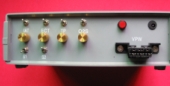
This is the ECU simulater tester for ISO 9141 protocol. It includes a ISO 9141 ECU module, 4 sensors with adjuster and switch. This item is very useful for car diagnostic tool engineers and sellers.
Features
- OBD2 CONNECTOR
- POWER PLUG SOCKET
- POWER BUTTON
- IAT SENSOR, WITH ADJUSTER AND SWITCH
- ECT SENSOR, WITH ADJUSTER AND SWITCH
- TP SENSOR, WITH ADJUSTER AND SWITCH
- MAP SENSOR, WITH ADJUSTER AND SWITCH
- ST SWITCH
- STP SWITCH
- ELS SWITCH
- PNP SWITCH

PWM ECU SIMULATION TESTER
This is the ECU simulater tester for PWM protocol. It includes a PWM ECU module, 4 sensors with adjuster and switch for sensor signals. This item is very useful for car diagnostic tool engineers and sellers.
Features
- OBD2 CONNECTOR
- POWER PLUG SOCKET
- POWER BUTTON
- IAT SENSOR, WITH ADJUSTER AND SWITCH
- ECT SENSOR, WITH ADJUSTER AND SWITCH
- O2 SENSOR, WITH ADJUSTER AND SWITCH
VPW ECU SIMULATION TESTER
This is the ECU simulater tester for VPW protocol. It includes a VPW ECU module, 4 sensors with adjuster and switch for sensor signals. This item is very useful for car diagnostic tool engineers and sellers.
Features
- OBD2 CONNECTOR
- POWER PLUG SOCKET
- POWER BUTTON
- IAT SENSOR, WITH ADJUSTER AND SWITCH
- ECT SENSOR, WITH ADJUSTER AND SWITCH
- TP SENSOR, WITH ADJUSTER AND SWITCH
- O2 SENSOR
- S1 SWITCH
- S2 SWITCH

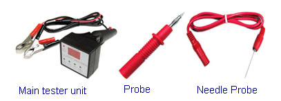
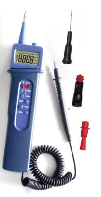
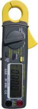
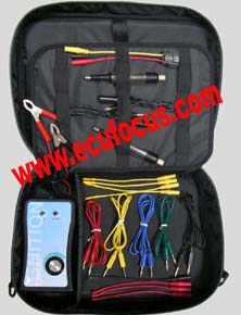
SMART AUTO CIRCUIT TESTER
This is a smart tool for auto egineerer. It can be used to test the voltage, and check circuit continuity. Every technician should have one of this pen.
To test the voltage: Turn the switch to the VOLT, connect the clip to GND, the voltage value and waveform will be displayed on the screen, if the voltage value is larger than 0.5V, the blue LED lights on.
To test circuit continuity: Turn the switch to CIRC.If the clip is short to the test pen, the red LED lights on, the screen will display the message as shown in the left figure; Otherwise, if the clip is open to the test pen, the screen will display the message as shown in the left figure.
To power off the VoltPen: Turn the switch to OFF. Power off automatically after a few minutes, Before you can use it again, turn the switch to OFF first, then wait for 10 seconds.
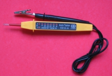
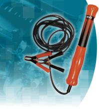
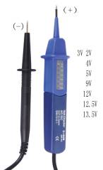
LED AUTO ELECTRONIC SYSTEM TESTING PEN
Automotive Digital Voltage Tester
Suitable for checking continuity/broken wires finding line wires, D.C. voltage LED display 2, 3, 4, 5, 12 , 12.5, 13.5V
vehicle battery testing
Spark plug ignition voltage test.
Sensor input and output signals test
Suitable for 12V/D.C. systems
For checking continuity/broken wires, finding live wires, other D.C. voltage testing from 0-12V, vehicle battery
Suitable for checking continuity/broken wires finding line wires, D.C
voltage LED display 2, 3, 4, 5, 12 , 12.5, 13.5V,
vehicle battery testing
Spark plug ignition voltage test
Sensor input and output signals test
Suitable for 12V/D.C. systems
For checking continuity/broken wires, finding live wires, other D.C. voltage
testing from 0-12V,vehicle battery testing spark plug ignition voltage test.
Specification
Voltage Range:2V/3V/4V/5V/9V/12V/12.5V/13.5V
Indication:LED lights up to the Voltage
Frequency range:0Hz-60Hz
testing spark plug ignition voltage test.
Ignition Coil Tester
Function:
Fast, simple and accurate of way to determine the defects in the ignition coils.
Automatic distinguish different ignition coil type by auto switching control modes.
Adjustable Frequency control ranging from 120Hz ~ 12 KHz.
Safety and foolproof.
Applicable on coil-on-plug (COP), coil-near- plug (CNP), double ended coil-on-plug (DECOP) or wasted plug systems.
Simple operation:
Connect power from 12Volts car battery and the power LED will light up.
Insert the yellow banana plug to the yellow socket and connect the cable to the control terminal of the ignition coil.
Hook up the spark tester to the ignition coil.
Turn ON the frequency knob and adjust the frequency from low to high (clockwise).
Turn back to low frequency and observe the spark color which should be bluish purple.
Increase the frequency gradually and observe the spark line. It should be in a straight line when NORMAL. If the spark line is curved, it indicates that the coil is aging or there is an internal leakage.
Turn to maximum frequency until the coil is slightly warm, then turn down the frequency and observe the spark line whether it is continuous or intermittent. If arcing sound is heard but no spark indicates that there is internal leakage.
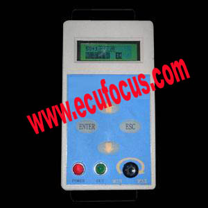
LOGIC CIRCUIT TESTER
Safe, convenient and easy to operate with dual-identifications (sight and sound), short circuit protection, digital display and alert sounds.
Designed for testing of electrical components and circuits with 6 functions:
Voltage measurement
DC12V output (Max 10A) for simulation
Positive (+) supply detection
High current ground testing
Low current ground testing (Below 1Amp)
Frequency adjustable output for simulation
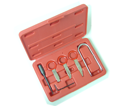
OTHER TOOLS
|